Wakeboard
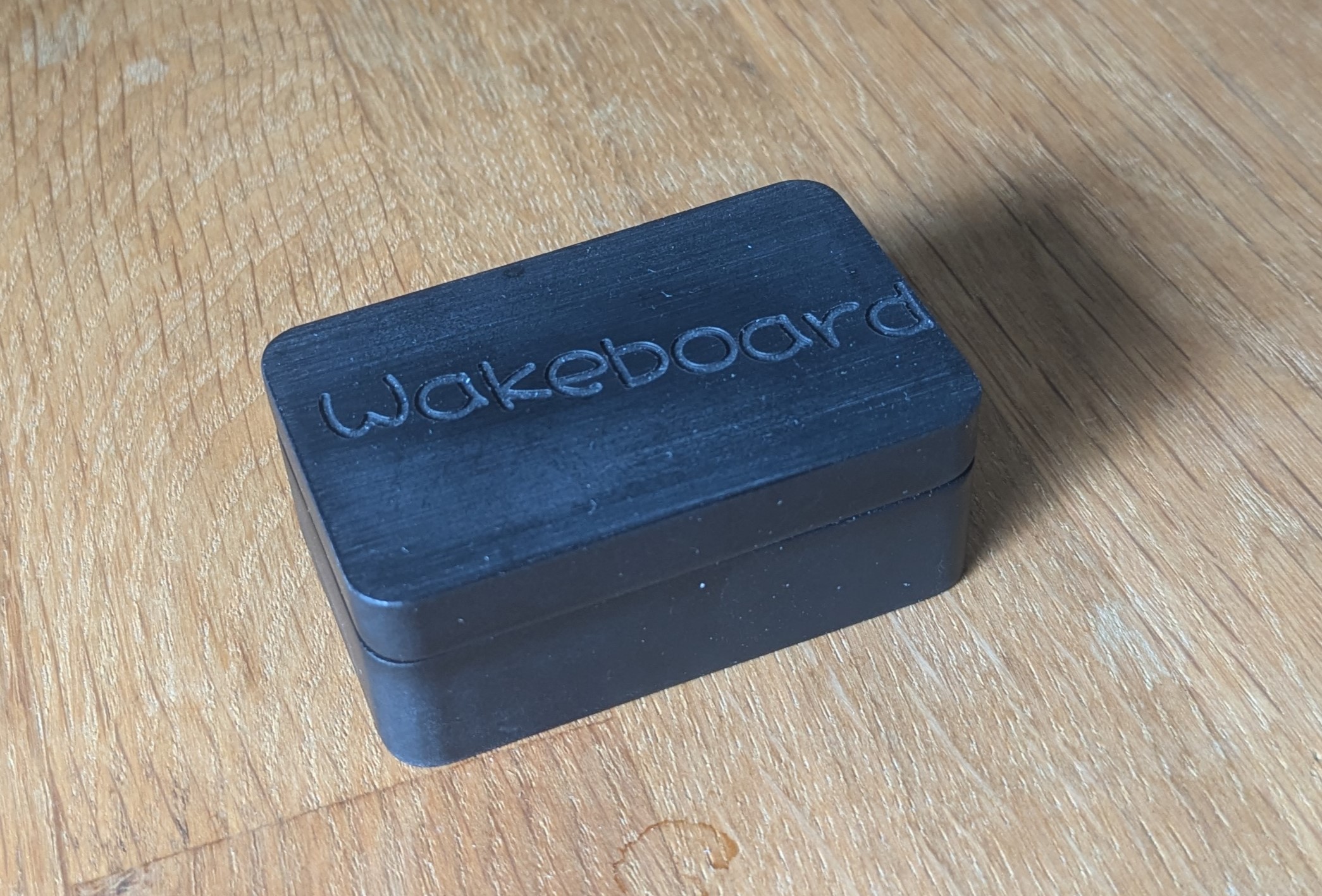
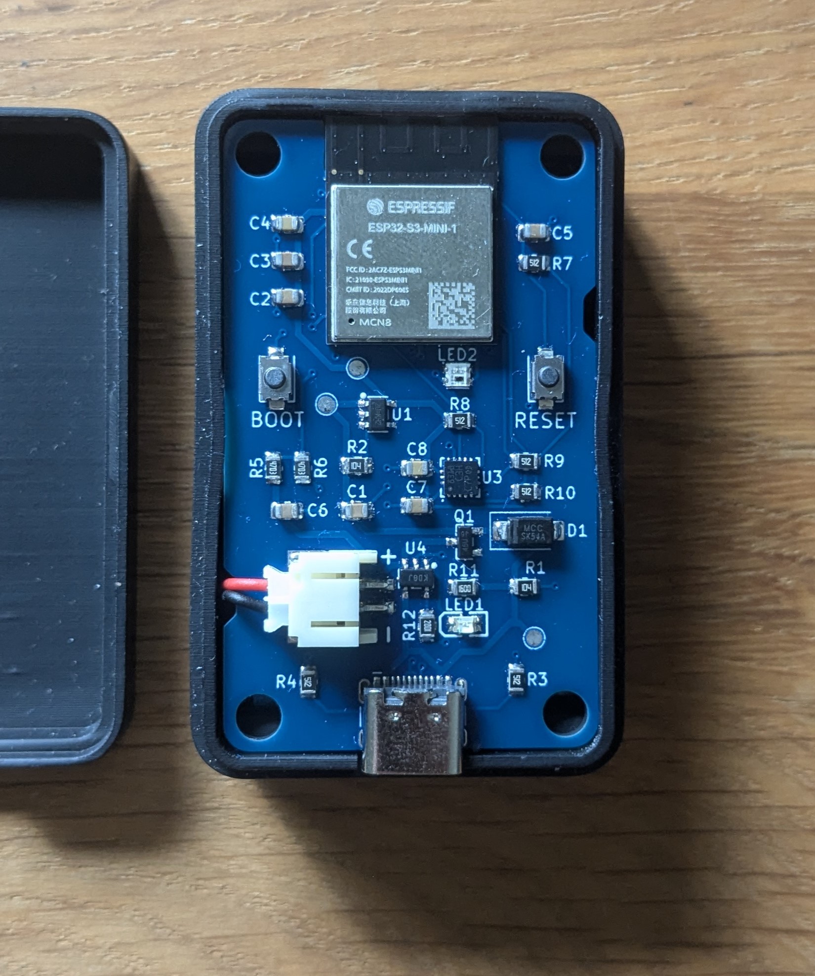
Wakeboard is a custom PCB I designed which combines an ESP32 S3 and an accelerometer. It’s designed to sit on top of my washing machine and alert me when a washing cycle is complete. I also designed a custom 3D printed case for it.
Prototype
A while ago, I built the initial version around the Wemos Lolin ESP32 dev board and an LIS3DH breakout board
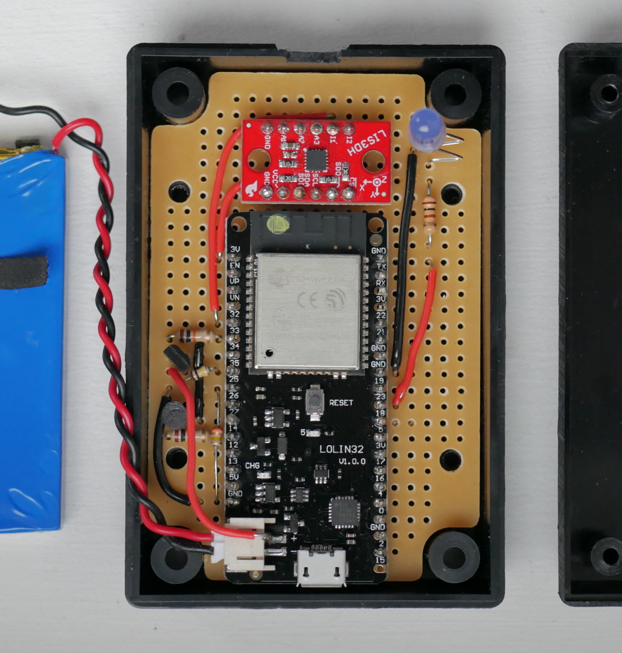
The prototype had a few disadvantages the biggest being higher power usage. The prototype would consume about 130 uA meaning it could sit in deepsleep mode for about 6 weeks before requiring a recharge.
PCB Design
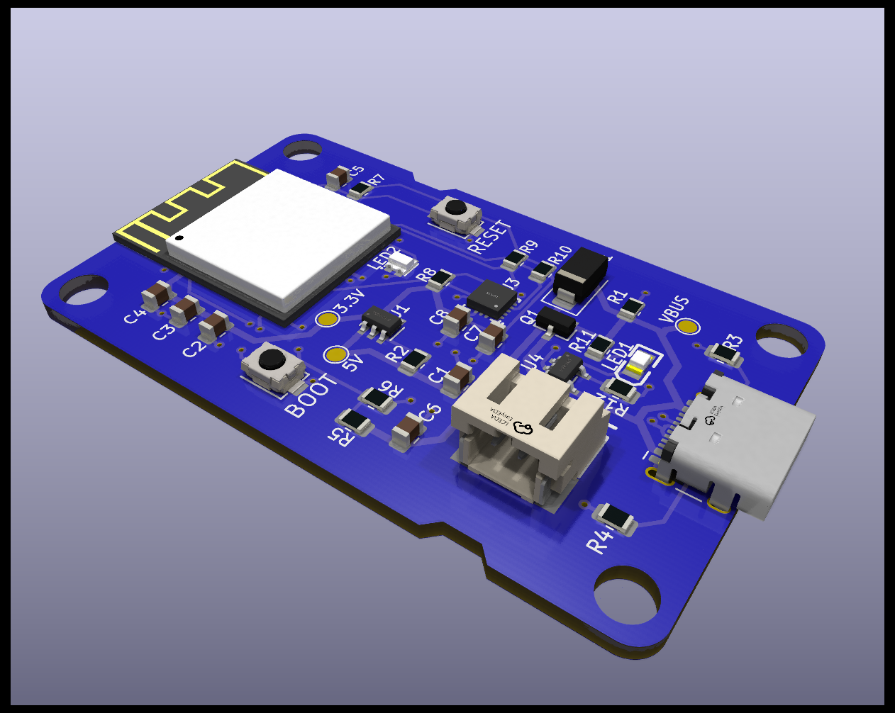
I had basically no PCB design experience before this project. However, it’s possible to learn a lot from the designs of other makers as well as from watching plenty of tutorials on YouTube. I borrowed heavily from the schematics of SmartBee’s BeeS3 and Bee Data Logger. One important lesson I learnt during this process it to ensure I chose components that are available on LCSC (the parts supplier for JLCPCB). To make this easier, I found a python script that takes an LCSC part number and downloads the part’s symbol, footprint and 3D model making it easy to import into KiCad. I chose to use 0805 sizes for the small SMD components as this is just about as small as you can reasonably manage when it comes to hand assembly. At this point, the design process was just a matter of placing components down and drawing wires between all the pins that needed to be connected.
When all the components are wired together on the schematic, the PCB design process involves positioning them on the board. Given my lack of experience, this took quite a lot of iteration before all the components were in a position that they could be connected with traces without causing conflicts. I wanted to stick to using just 2 layers because 2-layer boards are much cheaper to order.
Impedance Matching
One thing you will hear when trying to wire USB data lines is that they should be impedance matched. This means that their resistance should be calibrated such that “echos” in the data signals are minimised. After reading a dozen guides on this topic I was left more confused than before. I decided to just choose trace widths slightly arbitrarily and wait until the board arrived to see if I encountered any problems. It turns out that as long as your data speeds are slow impedance matching is less important. In the case of the ESP32 S3, it connects to the USB host at Full Speed which is actually the second-slowest USB speed and this seems perfectly fine for uploading firmware without any impedance matching.

Firmware
The design of the algorithm is quite simple:
The LIS3DH accelerometer that I am using has a feature that allows you to configure it to trigger an interrupt when a certain threshold of movement is reached. The exact values can be configured dynamically but I discovered through trial and error that when the accelerometer detects 15 seconds of 192 milli-gs of acceleration that means the washing machine is in full-spin. When the interrupt fires, it briefly wakes up the ESP32 which then sleeps for 40 minutes before waking in order to send a message to my phone. All this means that 99% of the time, the device is in deepsleep mode and consumes very little power.
Micropython
The code was written in micropython which I found significantly easier to work with than C. I’d highly recommend micropython when working with the ESP32. As you can see the code is fairly easy to follow:
    def start(self):

        print('Device woke')
        self.blink(1) # Blink the LED once

        reason = machine.wake_reason()

        print('Got wake reason: ', reason)
        if reason == machine.TIMER_WAKE:
            self.blink(1)
            print('Woke due to timer')
            print('Checking for new params')
            self.check_new_params()
            print('Sending notification')
            self.send_notification()
        elif reason == machine.PIN_WAKE:
            self.blink(2)
            print('Woke due to interrupt')
            print('Going to deepsleep')
            self.sleep_before_notification()
        else:
            print('Sleeping for 30 seconds')
            # Loop required so that we can push new code
            # You need to reset (press the button) to get to this part
            for i in range(0, 30):
                print(i)
                time.sleep(1)

        print('Loading accelerometer settings before going to sleep')
        self.load_settings()

        print('Going to deepsleep')
        self.wait_for_next_wake()
Telegram bot
To send a notification to my phone, I used Telegram’s API to create a bot. This not only allows the device to send messages to my phone but also allows me to send messages to the device.
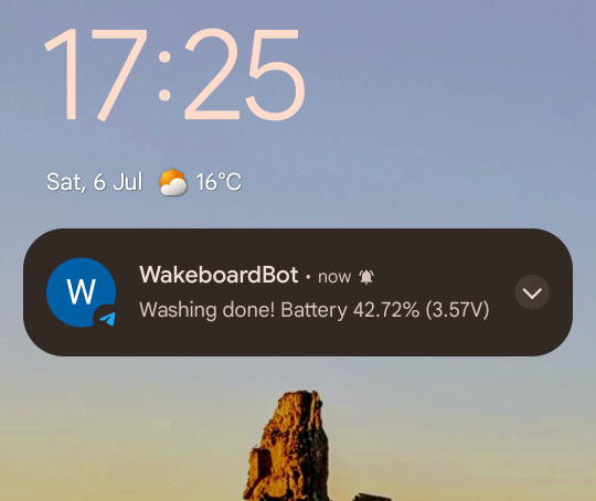
I can also set the sensitivity thresholds by sending a command:

Assembly
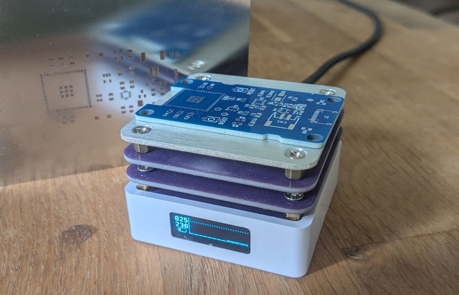
After ordering the PCB from JLCPCB and the components from LCSC, I applied solder paste to the board with the help of the provided stencil. Then each component was carefully placed with the help of some angled tweezers. I then used this very cheap 65W USC-C hotplate to melt the solder. The cost including shipping for five PCBs and one stencil was £19.24 and the total cost including shipping of the components (excluding battery) was £29.17.
Enclosure
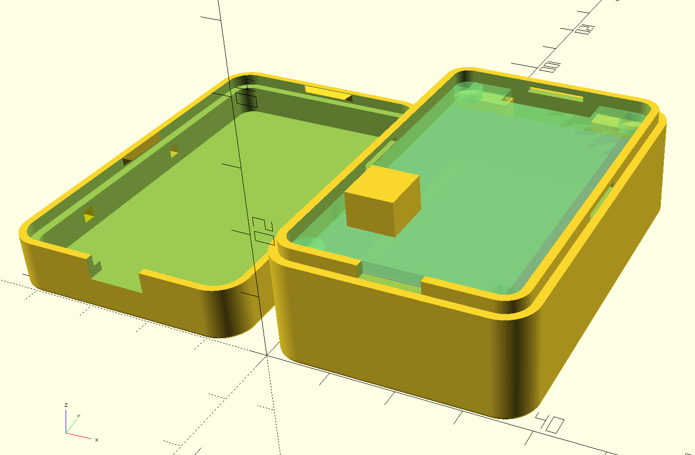
Finally, I wanted to design an enclosure for the board and the battery. Again, this was something completely new to me but as a coder, I was drawn to the app OpenSCAD which allows you to construct 3D shapes by describing them using a python-like language.
I had to go through multiple designs and iterations before settling on the final design. Perhaps the trickiest thing to get right was the tabs that would allow the lid to clip on and off. This is a form of snap fit enclosure where the tabs on the lid latch onto the slots in the base. Another consideration was making room for 4 magnets to place in the base so that the device can sit securely on top of the washing machine. The print was ordered from JLCPCB for just £6.78 including shipping.
Usage
So far the device has been running for three months reliably detecting and notifying when my washing is complete and has used only 1% of its 2000 mAh battery. This is actually much better battery drain than I expected and it is actually hard to believe the battery can last this long. However I have confirmed my voltage readings using a multimeter so it remains to be seen just how many months the device can last before requiring a recharge. I will update this post when the battery finally dies.
The micropython code is available here: https://github.com/alexspurling/micropython-washingmachine
The enclosure and KiCad project files are available here: https://github.com/alexspurling/wakeboard

